![]()
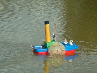 |
A friend had built a novelty paddle steamer "PS Panjandrum" and wanted an engine sound effect. I found a guy selling PIC chips programmed as psuedo random noise generators which gave a nice "hiss"and the boat had a microswitch operated by a cam on the paddle shaft to cyclically interrupt it. Testing the unit prior to installation I coupled the enable input of the PRNG to a (square wave) signal generator - this had a wide wide frequency range and adjustable mark/space and idly turning up the speed from the required "chuff, chuff" I started to hear a sound not unlike a first world war aero engine ticking over. Playing with the mark/space had interesting effects too. Much later on I discovered the PICAXE 08 chip and became aware that passing arguments 128 to 255 to the PICAXE "sound" command produced random noise of ascending pitch. So remembering my earlier discovery I began experimenting at the "hissy" end of the scale. By letting out slices of noise of varying pitch and duration in a cyclic manner (to give the engine a characteristic 'beat') I rapidly had an algorithm to use. |
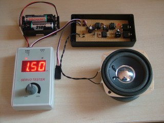
I reasoned that internal combustion engines produced puffs of exhaust gas from each cylinder in turn so that was probably the reason why this algorithm was successful. Tweaking the values to get the final results took days of experimentation nearly costing me my sanity and hearing! To alter the 'speed' of the engine I varied the gap between each slice of noise - this was updated once per rev by reading a pot on the ADC input (the speed demand input needs to be rapidly acquired as it is part of the engine loop). So to make a complete unit, a further PICAXE 08 was pressed into service to read an RC input and adjust the mark/space of a PWM stream accordingly. This stream was low pass filtered by a resistor/capacitor and fed to the ADC input of the sound chip. I also needed to include a lookup table to linearise the otherwise reciprocal characteristic of the engine algorithm. The auto-start on throttle, time-out on idling, startup and rundown sounds, cylinder count configuration etc were also required to complete the product of course.
|
I'd been getting my electronic components (including PICAXEs) by calling in at Technobots who, at that time, were local to me. Chatting with Paul Cooper (Mr T), he was keen to promote interest in and sales of PICAXE chips and I was persuaded to publish a DIY article on the Technobots website describing the engine sound unit. This article was duplicated on the Solent Radio Control Model Boat Club (SRCMBC) site. A Youtube video of the prototype was also published in 2009 (58,000 views to present date). That opened the flood gates and I came to dread opening my e-mail every morning as enthusiasts with little or no soldering and breadboarding skills wanted me to help to get their units going. Solder bridges, solder whiskers, incompletely cut veroboard tracks, misplaced veroboard cuts, wrongly identified resistors, components misaligned with their correct positions, problems installing the PICAXE Programming Editor . . . . . . I'm sure you get the picture! I realise that might sound rather arrogant of me, but I was in my own back yard here and these guys could build exquisitely detailed boats whereas my efforts used Flora tubs for the cabins and toilet rolls for the funnels - each to his own! |
|
|
|
So, given the popularity of the unit, to sidestep this issue a PCB was designed and from then on the constructional details and code were removed from the Technobots and SRCMBC sites and units were supplied ready made. |
|
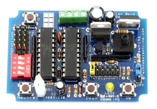
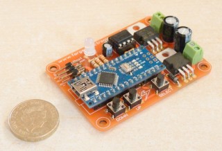
Later on the 20M2 PICAXE came to my attention and with 11 ADCs and far more memory I thought I could make a unit where parameters like tickover, top speed etc could all be pot adjustable. A protype was shown on Youtube in 2010 - almost 14,000 views to present date. By 2012 I'd finalised the design now using a jumper on a set of headers to select the parameters and '+' and '-' buttons to make adjustments. A PCB was designed and the unit was again marketed by Technobots - almost 21,000 Youtube views of this unit to present date. By now I'd developed a method of adjusting the pitch and duration parameters for each cylinder in real time - previously it involved painstaking editing and re-programming - and this is a feature of the 20M2 based unit - users can design their own engine 'voices' in addition to the 10 factory presets. It has to be noted that not every pitch and/or duration makes a sensible sound, but there are plenty that do if you hunt them down. |
 |
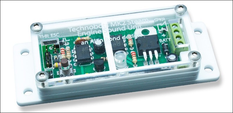 |
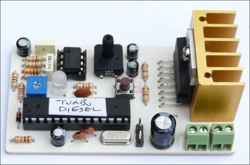
The launch of the vastly improved 08M2 chip finally gave me the impetus to revise the original 08 based sound unit. Still the same sound algorithm but taking advantage of improved memory, speed and new commands I was able to implement lots of 'voices' and adjustments. The novelty is that the unit is externally adjustable from the RC transmitter, using the throttle stick to adjust parameters. To avoid the boat responding during parameter adjustment a neutral (STOP) signal is passed to the ESC instead. The necessary inter-chip communication is achieved using the 15 step DAC to output various status and commands, the DAC level being read by an ADC in the receiving chip. |
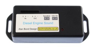
| Following an amicable agreement with Technobots, they are ceasing to supply the above unit and I've just released a (functionally identical) smaller version of it, packaged in a 3D printed case which I will market under the Forge Electronics banner. |  |
 |
Where do I go from here? I've successfully implemented the same sound sets on an Arduino Nano, altered the set-up to use 'select', 'up' & 'down' buttons and incorporated a user adjustable volume control which can also be set to cause the volume to increase with the speed, plus a (synthesized) horn that replaces the engine sound when operated. This works a treat but is on the back burner at present. |
| I've also been able to play wav files of 'real' engine sounds embedded in the Arduino program memory, but file storage is limited to about 3 seconds of 8k sampled audio which is looped and played back at a speed proportional to the throttle setting. I don't propose to continue with this approach. |
|
|
|
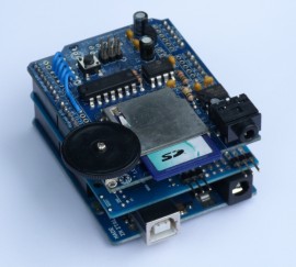
This is an early proof of concept unit storing audio files on an SD card using the Arduino WavShield. I have a microSD card adapter ready to interface to an Arduino Nano, but little time or enthusiasm to get on with it! |
| Currently all my efforts are being expended on variants of the model aircraft timer units (found elsewhere on this site) and a gun controller for model warships using stepper motors so a full 270 degree rotation (or even continuous rotation) can be achieved. The unit also has an mp3 player module with integral 3W amplifier for issuing the 'bang' plus it drives a remote white LED to give a muzzle flash. | 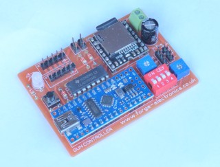 |
rhubarb, rhubarb, rhubarb
Technology Overview
Units from all manufacturers fall into two catgeories - those where the sound of an engine is digitally synthesists from electronic waveforms and those that replay recordings of the sound of real engines. The former usually have the advantage of lower cost and the latter have that of increased realism. If you are a serious marine modeller to the extent that you research the number of rivets on the hatches then you need to dig into your pocket for a recorded sound variant!
Synthesized Sound
There is a wide variety of sound quality in the available units - ranging from those sounding like a buzzy bee or a woodpecker on ecstacy to those that capture the beat and the spirit of an engine in much the way a cartoon captures a person's likeness yet lacks the accuracy of a photograph. I'd like to think my 'Combo' and 'Programmable' units are in the latter category, but you must judge for yourself. I believe the sound algorithm employed in my units to be unique and would advise that it is best suited to slow revving, 'slogging' engines typically found in fishing boats and tugs.
Recorded Sound
I know of no units that give truly authentic sound* but within the limitations of the technology employed they are leagues ahead of the synthesised sound units. The technology employed is to repeatedly play a short loop of sound and vary the playback rate according to the throttle demand to give the effect of the engine running through its rev range. Whilst this has the result of speeding up or slowing down the recording, it also has the side effect of changing the pitch of the sound at the same time, resulting in a Pinky & Perky effect (you may need to Google P&P unless you are of a certain age!). These links illustrate the problem using a passage of speech.
- original speech sample
- speeded up +50% (increased tempo AND increased pitch)
- speeded up +50% (increased tempo, unchanged pitch)
* for example the changes in volume and timbre when the engine is accelerating or being put under load are not catered for - but please enlighten me if you know different!
With certain engine types running over a limited rev range the results don't deviate far enough from real life to be unconvincing, but other engine types don't lend themselves well to this treatment. In the latter case some units attempt a compromise where two distinct sound samples are used - one for tickover, switching upbruptly to a quite different second sample for the remaining rev range.
Algorithms to adjust the tempo of a sound without altering its pitch do exist (that's how the third sound sample above was produced) - but they make a desktop computer sweat with the effort and as such these algorithms are unsuitable for real-time processing by the humble microcontrollers typically used in these engine sound units
There is also some skill involved in finding a good point in the sound sample at which to loop it. A poor 'join' manifests itself as a rhythmic 'hiccup' as the speed rises.
The FE100 and FE101 units I am currently developing are no better and no worse in these respects than the others out there in the market, but I hope to win out on price, size, ease of use and features.
Speaker Considerations
Inevitably the size and construction of a model may preclude the recommended speaker being used and if in addition the speaker installation is less than ideal, then both the volume and the quality of the sound will be compromised. If in any doubt as to a sound unit's capabilities, try connecting it to a music-centre loudspeaker and hear the result. Your model sounding any less rewarding than this represents the magnitude of your personal battle to defy the laws of acoustics!
Speakers are ideally mounted on a baffle – this is usually a piece of wood whose width is about twice the diameter of the cone with a hole in it about the size of the cone (determined by the speaker mounting arrangement). The purpose of the baffle is to prevent the anti-phase sound waves from the rear of the cone 'leaking' round to cancel out the in-phase sound waves from the front. Hi-Fi speaker cabinets are generally sealed to achieve this, though a carefully placed and sized hole in the cabinet can cause a phase delay to the sound waves from the rear of the speaker bringing them back into phase with those from the front thus re-inforcing the sound (especially the bass). The hull of a boat makes an excellent substitute if the speaker can be mounted beneath the cabin using the entire deck as a baffle and the sound can escape through open portholes, windows, doors or ventilation grilles in the superstructure.
Summary
Follow the links below to YouTube videos I've posted to hear examples of two of my sound units using the competing technologies. Expect to be disappointed if you listen on a laptop, tablet or smartphone, you need the fidelity of a desktop speaker system to fully appreciate them.
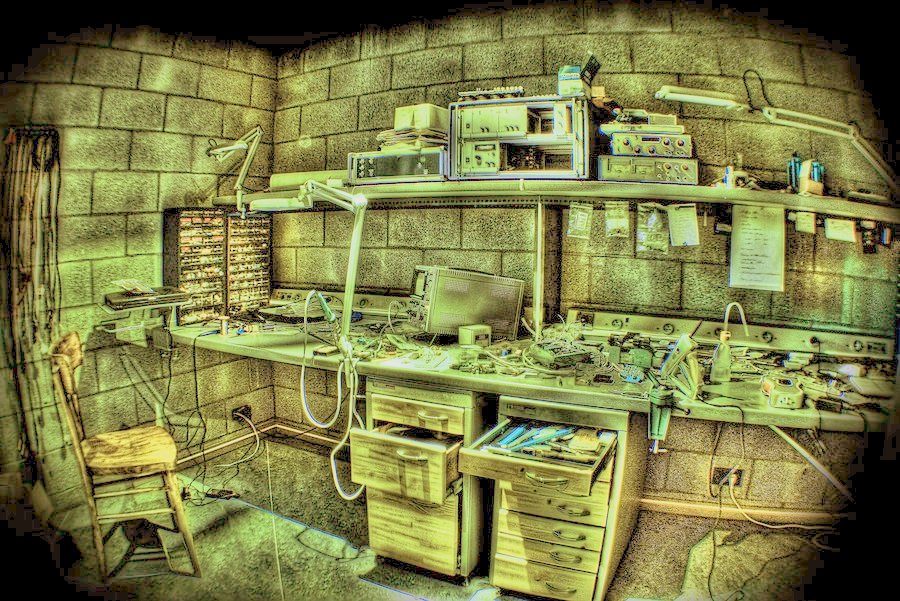
Here in my workshop I will be publishing articles giving an overview of the technology employed in and around these projects. Click on the links below or alternatively hover your mouse over the 'WORKSHOP' button in the main menu bar to see a drop-down list of these articles and <click> on your selection to access the article in question.
|
||||
- You are here:
-
Home

-
Workshop
-
Sound Unit History
- workshop