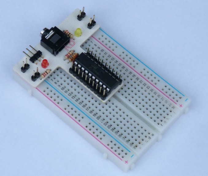
This is a simple hardware device to plug a PICAXE 20M2 microcontroller into a 400 point solderless breadboard with a power input wired to the chip and to each of the power bus side rails, a power indicator LED, PICAXE programming socket and an LED on the SEROUT line. I used a 3 pin header (RC servo format) for the power input as I'm doing a lot of RC work and have handy battery packs terminated this way - the 3 pin connector having the advantage of preventing application of reverse polarity. The long header pins that plug into the breadboard have been left sticking out above the PCB as test points.
 |
This has been particularly useful for developing the PICAXE 08M2 aircraft timer projects where I've sometimes used the SERIN and SEROUT pins for other than those purposes resulting in the inability to print debug data to the terminal and/or to re-program the chip in situ. However, by assigning labels for the hardware functions of the pins it only takes moments to adapt a working 20M2 program to operate in the target 08M2 hardware.
This PCB design is available free and may be downloaded from the link at the bottom of this page. The file is only available in Sprint-Layout format (*.lay6) but this is the preferred format for the isolation milling service I use here in the UK, and bypasses making a raft of Gerber files to submit. Contact details are given on the Isolation Milled PCBs page on this site.
View/Download:
| PCB Layout File | To permit upload/download of this file format it has been assigned a 'txt' file extension - after download amend the extension to 'lay6'. You will not be able to view this file unless you have a copy of 'Sprint-Layout', but it is sufficient to simply send it to my recommended milling service with your order. Should you wish to view the file you can download a demo version (save inhibited) or a free 'lay6' file viewer from their site. www.abacom-online.de/uk/html/sprint-layout.html |